
Hi Wiley:
I have heard of that, but Ive refrained from experimenting with it as I dont really understand the math
of it, how the involute is affected. Let me know what you finf, perhaps it will help.
Thx
Art
Bevel Machining diagram
Re: Bevel Machining diagram
Art,
I couldn't find the table that I was looking for in any of my old books, but I did find this explanation. http://www.archive.org/stream/americ.../n148/mode/1up . The explanation starts on about page 145.
Wiley
I couldn't find the table that I was looking for in any of my old books, but I did find this explanation. http://www.archive.org/stream/americ.../n148/mode/1up . The explanation starts on about page 145.
Wiley
-
Google Feedfetcher
- Full Member

- Posts: 125
- Joined: Tue Jan 06, 2026 4:56 pm
Re: Bevel Machining diagram
You still have to hand file the smaller end above the pitch line for the length of the tooth to correct the DP at the smaller end.
John S.
John S.
Re: Bevel Machining diagram
Hi Art,
Does your straight flute bit straight bevel gear cutting method allow you to leave the rotary axis at 90 degrees for all pitch cone angles?
--Justin
Does your straight flute bit straight bevel gear cutting method allow you to leave the rotary axis at 90 degrees for all pitch cone angles?
--Justin
Re: Bevel Machining diagram
Justin:
No, in all cases the 4th axis must be tilted to the cone angle so the cutting is perpendicular to the tooth profile.
Ill be looking into a waterline type of flat cutting for the fall re-release. Its my intention to have a much higher
level Gcode module so you can see the toolpaths and such as you setup for Gcode cutting.
Art
Re: Bevel Machining diagram
Hi Art,
You've obviously got more on your programming plate than I would ever dare to consume....
But just for the sake of conversation...
In your straight flute method, the cutter is cutting a plane, a vertical plane. And I assume that plane includes the apex of the pitch cone. If you imagine that plane is sticking to the tooth it just cut along, and you rotate the rotary axis to the horizontal, as one with the gear blank, the gear tooth, and the plane that was just cut, you will see that all it would take to make that plane vertical again is a rotation of the rotary axis. If the plane is vertical, you can cut it with your straight flute bit. Instead of an XY path, you would have an XYZ path, and the angle of the rotary axis would be slightly different.
It might be a simpler setup for some people than having to have and set up an angle plate to a very particular angle.
--Justin
Re: Bevel Machining diagram
Hi Justin:
That is one reason I think Ill do a module specificaly for such things. The reaosn for the tilt is that the vertical side of the flute is shaving the vertical wall of the tooth in a horizontal plane. Tilting the 4th axis allows the tooth plane to be horizontal, if it wasnt then the flutes vertical axis is having on a tilted axis, and the math indicates this shouldnt be allowed. Its very hard to picture and isnt very intuitive, but while its possible to do it
as an x,y,z in the case of a bevel untilted, the math more complex due the the elliptical shaped edge of the bottom of the bit when considered from the perspective of the tooth plane. (Im not sure Im explaining that very well, but its when you actually start to implement the model that the shortcomings come into play in the math of the tangental shaving routine. )
We'll have a much more detailed conversation about this as I get to the spot where a new Gcode module becomes necessary. Im currently working on the new spoking module to eliminate all the weirdness experienced by some with the various spokes as they get complex. The new one is just testing today and is extremely stable. I hope to add a dozen more spoke types and then start on adding all the variosu gears we currently have in GM, then its on to a new output module with new Gcode. At that point we'll begin a conversation about what types of operations people would like and in what orientations.
Art
-
Micheal Cranford
- Newbie
- Posts: 3
- Joined: Fri May 31, 2013 1:31 pm
Re: Bevel Machining diagram
That statement is not totally correct since wheel shaped (i.e. non-shaper) bevel gear cutters exist and have been inArtF wrote: Art said:
"An involute cutter wont work on a bevel as the tooth form shrinks as you approach the cone tip. Its this shrinking
involute form that usually the troublesome bit to do in a bevel."
use for many years. An involute spur gear cutter can easily be used to make straight cut bevel gears. Wheel shaped
(i.e. non-shaper) involute bevel gear cutters are simply thinner than standard involute spur gear cutters for the inner
face diameter clearance. Using a spur involute gear cutter to make bevel gears requires some geometric calculations
to determine which involute cutter to use, and it most commonly requires three passes per tooth. As the time permits
I can generate a spreadsheet to ease the calculations for the non-math inclined and, if possible, post it here if there is
any interest. It should be relatively trivial to add using involute gear cutters to Gearotic since the geometric motions
are much simpler than cutting out the tooth form using endmills.
The trick is to choose an involute form whose width is correct for the inner face diameter rather than the outer face
diameter. Doing this allows the first pass to cut the inner face involute form correctly. Then the 2nd and 3rd passes
are done by slightly rotating the gear blank and offsetting the cutter such that it exactly fits through the inner face
clearance that was created by the first pass. The 2nd and 3rd passes remove material from the adjacent gear faces
with the majority of material removal being done at the outer face diameter. This method does not require any filing
after the gear is cut (every gear is ready to use), unlike the similar method that selects the involute cutter based on
the outer face diameter. I have some four dozen different gear cutters and they can all be used to make bevel gears
just fine.
Re: Bevel Machining diagram
Micheal;
Point accepted and appears proper, however I lack expertise in this area and can't say for sure, but I do remember some issues existed as the cut approached the tip of the cone and tooth became really small. Art is away for a few weeks but I'm sure he'll reply with his thoughts on this matter upon his return. Anyone out there care to share their opinion on this?
Cheers
Bob ???
-
Micheal Cranford
- Newbie
- Posts: 3
- Joined: Fri May 31, 2013 1:31 pm
Re: Bevel Machining diagram
Bob:
I was being very brief in my first post, so to further expand on this there are at least two different styles of bevel gear tooth
profiles. The first type will be referred to here as straight bevel gears and the second style as parallel depth bevel gears.
In the former you can visualize the mated pair of bevel gears as being two cones with coincident apexes with a line of contact
between the two cones. The tooth shape at the maximum cone diameter is linearly scaled down as you approach the apex.
Hence the height and width of each tooth shrinks to zero at the apex. These type of bevel gears are generally made with a
specialize shaper rather than an involute cutter.
In the latter bevel gear type each gear tooth varies in width as you approach the apex but the tooth height could be constant.
I said "could be" because there are different ways of making parallel depth bevel gears using an involute cutter. In one method
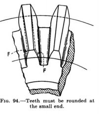
the maximum diameter defines the tooth shape so the smaller diameter end of each tooth needs filing so that the teeth are able
to mesh without interference. It's also the case that the involute cutter must be thinner than a normal involute cutter to fit into
the space between the teeth at the smaller diameter end.
In the easier to make method the smaller diameter of the bevel gear defines the tooth shape so a standard involute cutter can
be used instead of a bevel involute gear cutter. This method has the advantage that no filing is required to get the teeth to fit
with sufficient clearance. In both involute gear cutter methods multiple passes must be made with small rotations of the work
piece and small offsets applied to the cutter achieve the correct tooth width since that still varies with distance from the apex.
My original post was referring to the latter parallel depth method of making bevel gears.
I was being very brief in my first post, so to further expand on this there are at least two different styles of bevel gear tooth
profiles. The first type will be referred to here as straight bevel gears and the second style as parallel depth bevel gears.
In the former you can visualize the mated pair of bevel gears as being two cones with coincident apexes with a line of contact
between the two cones. The tooth shape at the maximum cone diameter is linearly scaled down as you approach the apex.
Hence the height and width of each tooth shrinks to zero at the apex. These type of bevel gears are generally made with a
specialize shaper rather than an involute cutter.
In the latter bevel gear type each gear tooth varies in width as you approach the apex but the tooth height could be constant.
I said "could be" because there are different ways of making parallel depth bevel gears using an involute cutter. In one method
the maximum diameter defines the tooth shape so the smaller diameter end of each tooth needs filing so that the teeth are able
to mesh without interference. It's also the case that the involute cutter must be thinner than a normal involute cutter to fit into
the space between the teeth at the smaller diameter end.
In the easier to make method the smaller diameter of the bevel gear defines the tooth shape so a standard involute cutter can
be used instead of a bevel involute gear cutter. This method has the advantage that no filing is required to get the teeth to fit
with sufficient clearance. In both involute gear cutter methods multiple passes must be made with small rotations of the work
piece and small offsets applied to the cutter achieve the correct tooth width since that still varies with distance from the apex.
My original post was referring to the latter parallel depth method of making bevel gears.