Page 4 of 7
Re: Gearify
Posted: Fri Sep 25, 2015 4:14 pm
by Nate
Gearify wrote:
Here is my question for you though, Nate. By whatever definition you're working with, what is the pressure angle measured from on a non-circular gear? In circular gears, the line tangent to the roll lines at the point of contact is always perpendicular to the line through the centers of rotation (which gives us some nice properties). On non-circular gears (especially the more eccentric ones) the tangent line can be quite far from perpendicular to the line through the center.
I don't know what the official definition is or even if there is one for non-circular gears. Art and I discussed the same question in the other thread. As far as I'm concerned, the preferred usage is the angle off p1-p2.
If measured from (p1-p2) I feel that there would be severe disortions where t1-t2 differs significantly. But if from t1-t2, the gears may not "push" on eachother properly and the entire benefit of involute teeth is compromised.
Thoughts?
Mechanically speaking you probably want to measure the angle from p1-p2 and live with the distortions. That's what I was trying to describe, and, mechanically, you want the action to be close to that line. There's a lot of freedom in tooth profiles, so the roll line tangent line can somtimes also work.
In the illustration, if we imagine that we're turning the red gear clockwise as the master and the yellow gear is the slave and the gear flanks are roughly perpendicular to the t1-t2 line, then it's likely that the gears would just separate.
Re: Gearify
Posted: Fri Sep 25, 2015 4:16 pm
by Nate
Nate wrote:
Gearify wrote:
Here is my question for you though, Nate. By whatever definition you're working with, what is the pressure angle measured from on a non-circular gear? In circular gears, the line tangent to the roll lines at the point of contact is always perpendicular to the line through the centers of rotation (which gives us some nice properties). On non-circular gears (especially the more eccentric ones) the tangent line can be quite far from perpendicular to the line through the center.
I don't know what the official definition is or even if there is one for non-circular gears. Art and I discussed the same question in the other thread. As far as I'm concerned, the preferred usage is the angle off p1-p2, but I worked this stuff out for myself. Other people will have other notions.
If measured from (p1-p2) I feel that there would be severe disortions where t1-t2 differs significantly. But if from t1-t2, the gears may not "push" on eachother properly and the entire benefit of involute teeth is compromised.
Thoughts?
Mechanically speaking you probably want to measure the angle from p1-p2 and live with the distortions. That's what I was trying to describe, and, mechanically, you want the action to be close to that line. There's a lot of freedom in tooth profiles, so the roll line tangent line can somtimes also work.
In the illustration, if we imagine that we're turning the red gear clockwise as the master and the yellow gear is the slave and the gear flanks are roughly perpendicular to the t1-t2 line, then it's likely that the gears would just separate.
Re: Gearify
Posted: Fri Sep 25, 2015 5:10 pm
by Gearify
"so the roll line tangent line can somtimes also work."
Sounds like this could potentially be a user option! :D
I do wonder how the distortions would appear when the roll-tangent line is significantly off-normal to the center-to-center line...
Here is another question.
We can define the pressure lines as a series of "snap shots" where the line is chosen to pass through the contact point at a particular point in time. So there is in a sense a "jump" from one pressure line to the next as the position of the line switches for each tooth, to pass through the varying point of contact of the roll lines. This jump may produce some abrupt changes in stress and pressure that may be undesirable (am I wrong?).
One could, however, define a MOVING pressure line. Such a pressure line would always be intersecting the point of contact between the roll lines, and the point of contact would linearly travel along this "floating" pressure line.
This is similar to how a Cubic Bezier curve is generated. Imagine the green line below is our "floating" pressure line. The orientation of the line is defined by either of the two "pressure angle" notions we defined (this is constant if measured from (p2-p1) as described earlier, and continuous if measured from (t2-t1)), and the position of the line would be continuously defined by the point of contact on the roll lines...
What do you guys think?
Re: Gearify
Posted: Fri Sep 25, 2015 6:54 pm
by ArtF
I think youll find the pressure angle is measured not from the pitch circle, but from the base circle, so if we shrink the ellipse by the base circle amount,
then compute a tangent between the two offset base ellipses, that would be the pressure angle Id use ( and do currently) in computing the involutes.
I think Nates idea is a really good one. Ill probably play with it in the coming months to see if it improves on hobbing, but I have read papers
on the hobbing being superiour simply because it deals with degenerate solutions to Nates idea. Its like the tips of the teeth on high K areas
of the curve, the hob finds it naturally, the involute equations start to produce some nasty overlap that needs to be dealt with.. at least thats
what Ive experienced so far.
Art
Re: Gearify
Posted: Fri Sep 25, 2015 6:58 pm
by ArtF
Michael:
As an example, in your drawing, Id imagine the proper line of action is if you moved T1 to a 1/4 inch inside the red on a line from
c1 to p1, and then places t2 at a line crossing pitchpoint to a point 1/4" inside the yellow...that woudl be the proper line for that gear.
Art
Re: Gearify
Posted: Fri Sep 25, 2015 7:43 pm
by Nate
ArtF wrote:
...
I think Nates idea is a really good one. Ill probably play with it in the coming months to see if it improves on hobbing, but I have read papers
on the hobbing being superiour simply because it deals with degenerate solutions to Nates idea. Its like the tips of the teeth on high K areas
of the curve, the hob finds it naturally, the involute equations start to produce some nasty overlap that needs to be dealt with.. at least thats
what Ive experienced so far.
...
Right, the hob is good for finding clearances, but if the profiles are degenerate, then 'virtual hobbing' will produce bad gears. (I.e. gears that lose mesh or with rotational ratios that are inconsistent with the roll lines.)
Re: Gearify
Posted: Fri Sep 25, 2015 8:03 pm
by Nate
Gearify wrote:
...
We can define the pressure lines as a series of "snap shots" where the line is chosen to pass through the contact point at a particular point in time. So there is in a sense a "jump" from one pressure line to the next as the position of the line switches for each tooth, to pass through the varying point of contact of the roll lines. This jump may produce some abrupt changes in stress and pressure that may be undesirable (am I wrong?).
One could, however, define a MOVING pressure line. Such a pressure line would always be intersecting the point of contact between the roll lines, and the point of contact would linearly travel along this "floating" pressure line.
...
The pressure line is stationary in the reference frame of the pitch point. In any reference frame where the pitch point is moving the pressure line will be moving as well.
In this video the pressure line is the red line, and the red dots are points of contact. Can you explain what time in the cycle the "jump" you're concerned about occurs?
https://www.youtube.com/watch?v=14yMFdgWM-A
Re: Gearify
Posted: Fri Sep 25, 2015 8:16 pm
by Gearify
Let's say that P(t) is the point of contact between the roll lines at time t. The line of action (as you defined it) passes through P(t), and is oriented based on the pressure angle.
Suppose the pitch point begins contact at time t0 and moves smoothly along the line of action until the next tooth is engaged at time t1. Now a new line of action is engaged and will pass through point P(t1).
For a circular gear, P(t0) = P(t1). for a non-circular gear, they are most likely not equal.
So imagine in the video you posted, imagine that the height of the red line would instantaneously jump to a different vertical height every time a new tooth engaged.
Re: Gearify
Posted: Fri Sep 25, 2015 8:48 pm
by Nate
Gearify wrote:...
So imagine in the video you posted, imagine that the height of the red line would instantaneously jump to a different vertical height every time a new tooth engaged.
The pitch point is moving continuously along a continuous path. There's also a continuous rotation. What does your math education tell you about the composition of continuous things? Also, does continuous motion 'instantaneously jump'?
The "dots" do jump back to the start of the line of action - that's the sawtooth phase I described - but the motion of the line of action as a whole is going to be continuous in any setting where the motion of the gears is continuous.
...
BTW: If we imagine that the gear in the video is rolling along a stationary rack, then the only way that P(t0) = P(t1) is if t0=t1. You're not thinking in terms of the reference frame of the pitch point.
Re: Gearify
Posted: Fri Sep 25, 2015 9:31 pm
by Gearify
I think I'm not communicating what I am trying to say properly. I do understand composition of continuous functions is continuous. I think we're talking about two different things but I'm not sure where our disconnect is yet.
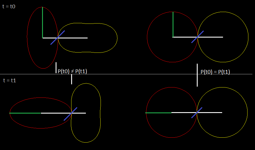
In the above diagram, the circular gear has a line of action who's position (I'm talking about the entire line segment's position) remains constant relative to (let's call it) the observer. But the non-circular gear has a line of action that is at a different horizontal location. So, either the horizontal position (relative to the observer) of the line of action would need to jump to new horizontal position after each tooth engagement, OR, the location of the line of action is allowed to vary continuously over a single tooth (in which case the "dots", which are interpolating across a moving line, would actually follow a continuous curve).
Do what I' m saying make more sense now?
